
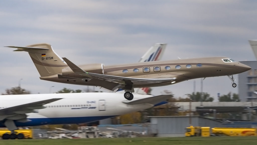
A Flight Data Recorder or FDR is a vital component required to be onboard all commercial aircraft. These devices record valuable information that can help determining the cause of an accident or incident and prevent them from occurring again in the future. However, even with this device onboard, without routine maintenance and annual maintenance readouts, the device can fail to provide useful information.
Flight Data Recorders are devices recording information deriving from a vast number of parameters during a flight. The purpose for recording and storing this data is to provide information after an aircraft incident or crash, in order to find the cause of the incident/accident and avoid the same or similar tragedy in the future.
Now days however, the FDR does more than just collect data for post-crash evaluation, and is utilized to provide information related to maintenance events or flight safety events and as a result prevent accidents from occurring in the first place.
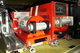
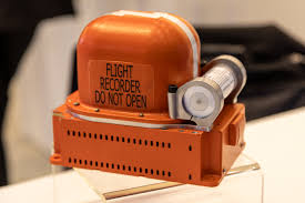
FDR data readouts provide information about the system’s integrity and also provide valuable data that can be vital during maintenance checks. The FDR is one of the two recorders fitted on aircraft with the Cockpit Voice Recorder or CVR providing cockpit audio information on flights.
The CVR records conversations between the pilots, communications with air traffic control, aural warnings from aircraft systems and ambient flight deck audio. Utilizing the FDR and CVR data via regular annual maintenance readouts, technicians can identify technical or operational issues, and even determine the life cycle of aircraft components.
Both FDR and CVR have become a single device which handles both roles. However the FDR has changed considerably since they first appeared on aircraft, drastically improving their performance and reliability, but where did all start?
History of the Flight Data Recorder
Flight Data Recorders where first used in the 30s on small aircraft. It wasn’t until 1958 where specifications for them start being used on their manufacturing, requiring them to be resistant to both high impact and fire to improve their chance of survival in the event of a crash.
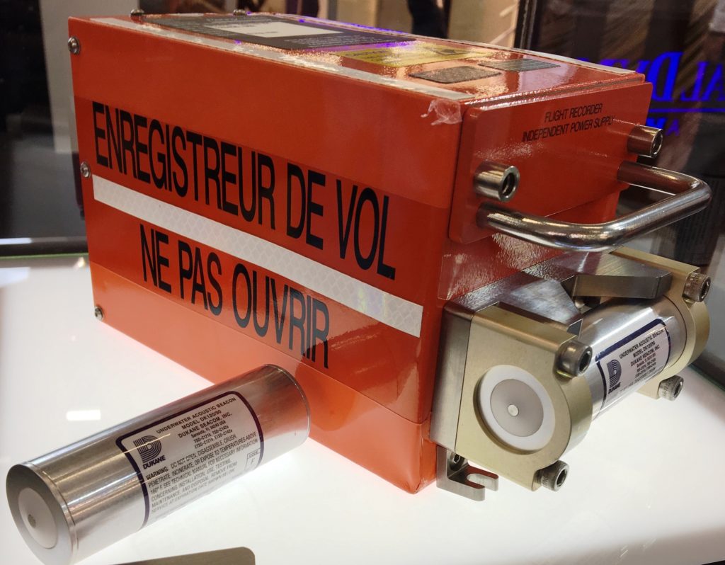
To do so, they were placed inside a casing, which is what we know as the Black Box, to house the device and protect it against environmental hazards. It was also requested for the casing to be of a vivid color, making it easy to spot on a crash site, and thus facilitating recovery.
 Metal Foil and Photographic Film Recorders
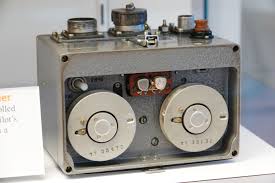 Metal Foil and Photographic Film Recorders
Metal Foil Flight Data Recorders where the earliest type of FDR used on commercial flights. they consist of a mechanical stylus which scribes long lines on a long sheet of steel foil. The metal was corrosive-resistant and hard enough to withstand high impact and temperatures. The data was received from basic sensors such as accelerometers and pitot tubes and was processed internally.
The Metal Foil FDR was replaced for the most part by the Photographic Flight Data Recorder. Photographic Film Recorders replaced the metal sheet with a photographic film, and the mechanical stylus with light beams. While better overall than its predecessor, both type of flight data recorders had the same issue; they could only monitor and record a limited number of parameters such as magnetic heading, altitude and airspeed.
Magnetic Tape Recorders
Magnetic tape based flight recorders were a considerable improvement of the previous generations, allowing the FDR to record an increased number of parameters. Magnetic Tape Recorders also allowed for the recording of cockpit voice recordings, the first use of a CVR.
The process of recording information was also different, as it no longer was recorded on a single stream. Instead, once the data was gathered, it was sampled, digitized, and multiplexed. This was afterwards recorded on a magnetic tape with simple signals to code in 0’s and 1’s.
Acquisition Units
Previously we mentioned the early Flight Data Recorder models processed the information internally once received. This proved to be inadequate once the FDR was able to handle more parameters, as was the case with magnetic devices.
In response to this, flight data acquisition devices were designed to collect all parameters before being recorded by the FDR. These devices are known as Flight Data Acquisition Units (FDAU), Flight Data Interface Units (FDIU) or Flight Data Acquisition Cards (FDAC). These devices process and organize the data in a specific format before being sent to the FDR for recording and storage.
However this technology was limited to public transport aircraft, smaller aircraft still relied on the FDR for both data acquisition and recording.
 Solid State Recorders
By 1985 the evolution of digital technologies allowed the replacement of magnetic tapes for solid state memory on flight data recorders. The recordings provided by an FDR with solid state memory had better quality and reliability.
In addition to the improved performance, the memory chips were becoming smaller and the number of recorded parameters went up to several hundred, sampling frequencies increased and recording times of some models increased to 50 hours or more.
Additionally, the quality of sound for the CVR was improved as the audio was digitally stored and the audio recording time was extended from half an hour to over 2 hours.
Non-Protected Flight Recorders
In the past, Flight Data Recorders were the only devices which collected flight information, and even then it was only accessed after a crash or a major event. However, with the introduction of data acquisition units, flight information can be directed to other devices besides the FDR.
These devices do not need to be within a protective case as a black box, they are designed to be removed and replaced quickly. Such devices can store information in a tape, an optical magnetic disc, a PCMCIA card or even a flash or SD card; and they are situated either in the cockpit, or the electronics bay.
The quick access recorders (QAR) record the same data as an FDR would for the most part, the data acquisition unit feeds the QAR the same information as the FDR. However, more recent QAR systems are compatible with standard data buses (ARINC 429), this means they can receive and store additional data.
Direct access recorders (DAR) in the other hand, receive data from data management units (DMU). DAR units allow users to select which parameters to record, as well as the sampling frequency; as well as setting the recording mode between periodic recording, or event triggered recording.
These data recording units are used for the purpose of flight monitoring, research, and maintenance.
How Data Acquisition Systems work
Data acquisition computers are in charge of centralizing and formatting data deriving from aircraft sensors, onboard computers and other data gathering devices and then feed this information to recording devices such as the FDR via a dedicated digital link (ARINC 573, 717 0r 429). There are 4 types of input data:
- Discrete: Logical status detection, indicators, switches, and relays
- Analog: potentiometers
- Synchronization transmitters
- Digital bus: ARINC 429
Data acquisition units create and feed a continuous stream of information to the FDR.
Data frame layout
The data frame layout depend on the type of recording system. They commonly describe the following details:
- The method used by the data acquisition system (location of parameters, number of bits used to encode parameters, conversion algorithms, and method of decoding).
- The functions used to convert the recorded value into the actual physical value. For each parameter, the conversion function is checked with the calibration of the measuring and processing channel, as mentioned later in this document.
Verifying recorded parameters
In order to be compliant with the mandated annual FDR data check, the inspected data must be deriving from the FDR, and not from the QAR or DAR.
The Flight Data Recorder data can be retrieved from the memory for analysis and conversion into engineering units, with the aid of decoding software previously programmed to handle the data for each aircraft type as per the applicable frame layout documentation.
The check on recorded parameters may include:
- Location of regulatory parameters in accordance with data frame layouts
- Validity of conversion functions for each regulatory parameter, taking into account their operational value range
- Coherence of parameters’ patterns for phases of flight
- Check for long or cyclical areas of unreadable data
- Chronological integrity of recordings
Aviation authorities provide examples of maintenance readout procedures.
Calibration of measuring and processing channels
In order to evaluate the quality of the recorded data a parameter’s value, as measured by instruments, must be compared with the recorded value.
Conversion algorithms provided by the manufacturers are theoretical, as they are simply the results of tests performed on prototypes. This makes calibrations necessary as the results may differ on the actual aircraft. It is also important to note that sensors used for recorders may also differ between aircraft; which can further alter the data recorded.
Furthermore, several factors can alter the quality of the measurements. These factors include:
- Sensor aging. Sensors are subject to environmental constraints like water or high temperature and pressure variations that can cause the system to drift from the initial calibration
- Connecting an additional device to an analog input, like a potentiometer or a synchronized transmitter. These additions can modify the electrical characteristics of the transmitted signal in terms of amplitude and/or phase
- The disassembly and reassembly of mechanical elements. This can cause some sensors to go out of adjustment and can happen during major overhauls or during an FDR system retrofit
When performing a maintenance calibration, should a high difference between the values be encountered, depending on the nature of the problem, one of these actions should be taken:
- Replacement or repair of malfunctioning component
- Modification of conversion functions in data frame layout documents, through a calibration procedure

Operational and regulatory aspects
Flight data recorders were implemented in the 50s, but regulations and requirements were implemented several years later. These regulations can be found in different texts; at the ICAO level, Annex 6 (eighth edition, July 2001) and Annex 13 are the main documents. At the European level the information is found in the JAR OPS1 document.
Annex 6
According to Annex 6, all aircraft with a maximum certificated take-off weight over 5,700 kg are required to be equipped with a Flight Data Recorder, regardless of the date of the individual certificate of airworthiness.
The parameters for aircraft with a maximum certificated take-off weight of over 27,000 kg also applies to aircraft with a maximum certificated take-off weight of over 5,700 kg and for which the individual certificate of airworthiness was first issued after 1 January 2005.
The rules for installing a Flight Data Recorder are as follows:
- Recording requirements on installed equipment must be verified by methods approved by the appropriate certifying authority
- The manufacturer must provide the national certifying authority with the following information concerning the FDR:
- Manufacturer’s operating instructions and installation procedures
- Parameter origin or source and equations which relate to conversions to units of measurement
- Manufacturer’s test reports
The Annex also explains how inspections should be carried out with the following steps:
- The read-out of the recorded data from the FDR should ensure that the recorder operates correctly for the nominal duration of the recording
- The analysis of the Flight Data Recorder should evaluate the quality of the recorded data to determine the nature and distribution of the errors
- The FDR data from a complete flight should be examined in engineering units to evaluate the validity of all recorded parameters. Thus, the engineered parameters processed from raw data must be examined
- Particular attention should be given to parameters from sensors dedicated to the FDR, because failures of these sensors cannot be detected by other onboard systems
- The read-out facility should have the necessary software to accurately convert the recorded values to engineering units and to determine the status of discrete signals. The use of software for these tasks is necessary in order to process all the compulsory parameters of a flight in a timely manner
- A report of the annual inspection should be made available on request to the State’s regulatory authority for monitoring purposes
The Annex specifies re-calibration of the FDR system should be performed at least every 5 years per the mandatory parameters. A re-calibration should also be performed every 2 years when the parameters of altitude and airspeed are provided by the sensors dedicated to the FDR.
JAR OPS 1 and OPS 1
It is specified in the JAR OPS1 that aircraft with a maximum certified take-off weight over 5,700 kg are required to be equipped with an FDR. The same regulation applies to multi engine turbine powered aircraft with a maximum passenger seating of 9.
The letter #98159 of the SFACT specifies how frequently parameter checks must be performed, depending on the following:
- FDR technology: the presence of a magnetic tape and rotating parts cause magnetic tape FDRs to age quicker, which imposes more frequent inspections than for the newer generation solid state FDRs
- Existence of a flight data analysis program that takes into account all required parameters. Such program allows for more time between inspections, provided that “the data source used for analysis is the same as for the FDR
Problems encountered during FDR operations
When performing an investigation utilizing FDR data, investigators can encounter different kinds of problems while handling the data. These are different categories of problems investigator bodies such as the BEA have come across:
- Missing or incomplete data
- Incomplete or unavailable data frame layout documents
- Calibration issues
It is important to keep in mind that while these are some frequent issue types encountered during investigations, these are not the only kind of problems that can be encountered, and operators should be ready to solve any kind of problems encountered.
Missing or incomplete data
There have been multiple cases of missing or incomplete data during Flight Data Recorder investigations. In all of these cases, the investigation was significantly slowed down by several weeks and even months; in some cases the investigation was impossible to complete.
Incomplete or unavailable data frame layout documents
There are cases where operators are unable to provide the investigating bodies with the data frame layout documents of the flight. When this happens, investigators try and get the required information from the manufacturer or another third party overseeing the information.
At times however, the information gathered from third parties can be inaccurate, incomplete, or incoherent. This can severely extend the investigation time by months as information must be verified and at times corrected; in some cases the investigation is not able to be completed.
Should the operators and third parties fail to provide any form of documentation, the FDR data cannot be analyzed, leaving the investigations unable to be completed.
Calibration issues
At times this kind of issues can prove to be confusing or involve erroneous readings. The cause of this issue could be an erroneous input of a serial number, a human error.
The impact of poor maintenance on investigations
 The impact of poor maintenance on investigations
It is not rare for investigating bodies to encounter these kinds of problems on investigations. As mentioned before, these errors slow down the investigation process and can cause the investigation to fail at times.
This kind of errors is detrimental to air safety, and most of the times can be avoided with proper management of maintenance. Poor data quality may be caused by the following:
- Inadequate FDR maintenance
- Data frame layout documents not being archived or updated, especially following a reprogrammed FDAU or a change of operator
- Incomplete check of recorded parameters
- Partial checking of the measuring and processing channels elements, which does not guarantee a satisfactory operation of the channel as a whole
Given the complexity of the regulations, it is highly possible that most of the problems caused during investigations is due to lack of knowledge on Flight Data Recorder systems. This is particularly true for most airlines with less than 100 employees. Whenever an FDR readout is requested, the following information should be provided to the maintenance team:
- Aircraft registration number
- Flight data acquisition unit manufacturer and part number
- Aircraft type
- Engine type
- FDR manufacturer and part number
While only the aircraft registration number is necessary when the parameters are already known; providing the rest of the information can be beneficial when information is not clear, and it can help avoid other problems during the maintenance.
Should the maintenance team lack the information on the FDR parameters, the information should be provided in order to proceed with the maintenance. This information can be retrieved through the following sources:
- The aircraft operator
- The aircraft manufacturer
- The acquisition unit manufacturer
Keep in mind the aircraft operator should have in their possession the information required to decode the FDR parameters, should the information be requested by a government investigation unit. Normally, the maintenance team will take 7 working days to perform readout of a known aircraft. However if the aircraft is not known, or if some required information is lacking, the process may take up to 14 business days, depending on the situation.
In order to make sure the FDR system is functioning properly and ensure it meets all regulations of FDR readout authorities, the FDR system should be checked annually to ensure that:
- The system is recording for the minimum duration (25 hours)
- The FDR data itself is being recorded correctly
- The parameters recorded by the FDR are correct
While the requirements of each investigating body and readout authority may vary, ensuring the above milestones should help prevent issues with data loss or compliance with regulatory requirements. It’s important to choose an appropriate readout provider which meets or exceeds regulatory requirements to ensure the tasks of FDR readouts and CVR readouts satisfy regulations and avoid problems in the event of an incident or investigation.
Contact us today and find out how to put OSPs expertise to work for you